![]()
![]() Synclavier
II restoration and upgrade
Synclavier
II restoration and upgrade
Page 3 of a pictorial record of the restoration of a Sync II in June 2005
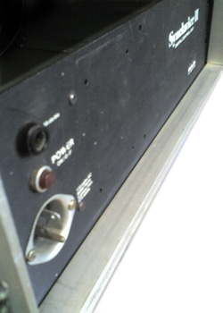
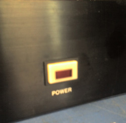
Step 10.
The original Sync II power panel.
Note the old style 110V input and the round, lit power switch.
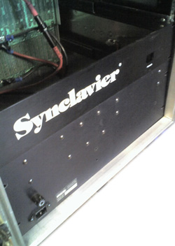
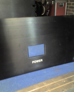
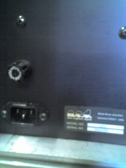
Replace panel with later version mains input and distribution panel. Note the use of an IEC connector on this version. The mains switch will be in a panel of its own with the infamous Synclavier logo in big white unmistakable letters. Sometimes it just feels right to show off the name.Step 12.
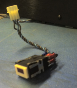
A new genuine Synclavier power switch complete with original loom (unshielded connectors, we will have to cover the exposed mains later) Switch fitted to the panel before and after.
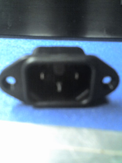
Step 14. The power panel IEC connector as fitted standard has given problems in the past by overheating and corroding, causing further overheating and finally in extreme cases, meltdown
Fit a high current, high temperature input connector. Note the extra guide lug at the top which prevents the usage of a normal rated IEC mains lead. Only high current leads may be used with this connector.Step 16
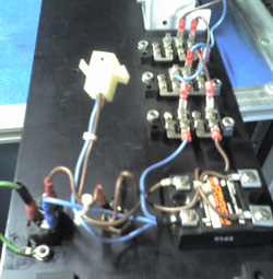
The high current input connector now fitted and wired. A Solid State Relay (not present in the standard Sync II) is now fitted to take the strain away from the main switch, and the output is fed to the distribution blocks that are standard Synclavier items.
We will update the pictures daily until the upgrade is complete.
If you wish to purchase a fully restored Synclavier with a full warranty, please e-mail us at synclavier@500sound.com
Either close this page to return to the previous page or click here for the home page
©Copyright 2005 The page, its contents and pictures are copyrighted by Synclavier Europe. Do not use any part of this page without express permission from Synclavier European Services. a whole new experience.